The Spark of Inspiration
Ten years ago, standing on the corner of my property, I envisioned a project that would not only enhance the aesthetic appeal of my fence but also challenge my engineering skills. The idea was simple yet ambitious: to adorn each of the fence posts along the 600-foot boundary with clusters of WS2812B LEDs. The concept was to create a mesmerizing light display that could be seen from the two roads hugging our corner lot. However, I quickly encountered a significant hurdle—the signal stability of these LEDs over the 10-foot distance between each post.
Tinkering and Troubleshooting
Undeterred by the limitations of WS2812B LEDs, I turned to RS485 chips, hoping their robust signaling capabilities could bridge the distances I was dealing with. The journey from prototyping boards at my kitchen table to designing and ordering custom PCBs was filled with soldering, testing, and more soldering. Yet, despite my efforts and enthusiasm, the results were far from what I had envisioned. Life, with its myriad distractions, eventually led me to shelf the project, leaving behind a trail of unfinished PCBs and unresolved challenges.
A Renaissance of Innovation
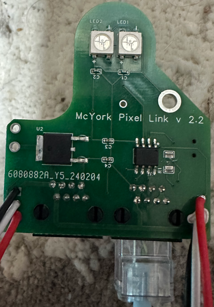
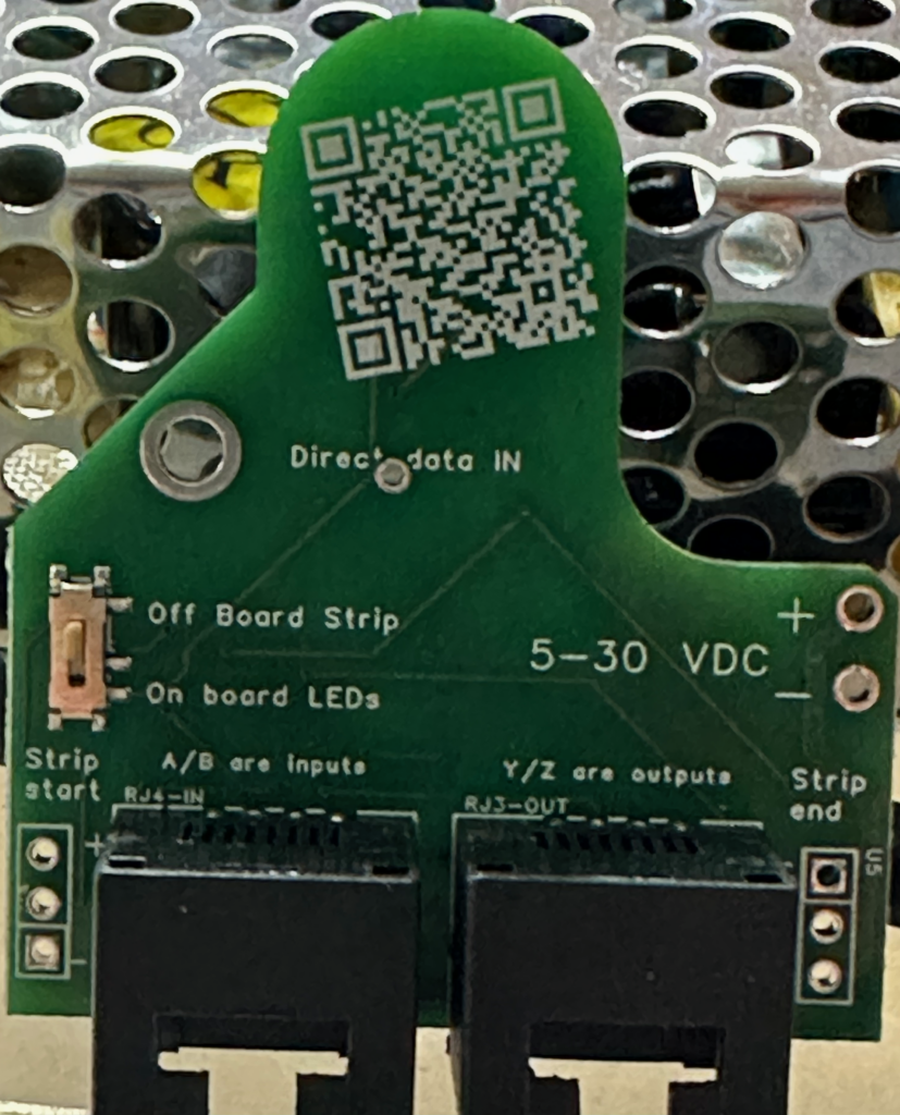
Fast forward to a December not long ago, a breakthrough in design software rekindled my passion for the project. This new tool not only allowed me to visualize my designs with ease but also offered PCB manufacturing and component assembly services. Suddenly, the daunting tasks of building and soldering were no longer barriers to progress. The ability to quickly iterate designs without the manual labor previously required was a game-changer. My project was back on track, evolving from its initial version to the more refined iterations of versions 2.0 through 2.3.
Refinements and Revelations
With each new version, my understanding of the project and its requirements deepened. The transition from a 10-pin RS485 chip to an 8-pin MAX490 marked a significant turning point, optimizing signal transmission without sacrificing speed. The addition of a switch for external LED connections and improvements in copper routing reflected my growing confidence and competence.
However, this journey was not without its setbacks. A lack of polarity and over-voltage protection led to several boards meeting their untimely demise—a stark reminder of the importance of incorporating protective measures in circuit design.
Looking Ahead: Version 2.4 and Beyond
As I await the arrival of version 2.3, with its enhanced power section and anticipation for the introduction of polarity protection in version 2.4, I reflect on the journey thus far. The path from a dream to a tangible, functional project has been fraught with challenges, learning opportunities, and moments of triumph.
This project, born from a desire to light up a fence line, has illuminated much more than that. It has been a journey of persistence, innovation, and continuous learning. As I look forward to further iterations and improvements, I am reminded that the process—the tinkering, troubleshooting, and iterating—is just as important as the final product.
To those embarking on their own DIY projects, remember that every setback is a setup for a comeback. Embrace the challenges, learn from your mistakes, and never underestimate the power of innovation and persistence.


