Why Use Pixel Link
Pixel Link offers a powerful solution for using WS2812B addressable LEDs across long distances. With Pixel Link, you can:
– Theoretically extend LED installations up to 4000 feet, with practical tested distances of over 1000 feet.
– Create large-scale art installations with programmable lighting across different areas.
– Enhance intricate lighting displays, such as sophisticated Christmas light setups.
– Implement permanent installations incorporating innovative lighting.
Pixel Link’s ability to transmit TTL signals over significant distances sets it apart. With a bandwidth minimum of 800kbps and potential peaks up to 2.5Mbps, it opens up possibilities for various innovative applications beyond just lighting.
Overview of Pixel Link 4.1
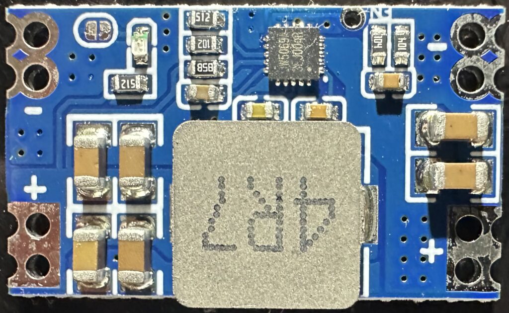
Pixel Link 4.1 is the latest iteration of our long-distance LED control system. This version uses a modular power supply approach, with power management components that are soldered directly to the board.
Key Features:
- Compatible with WS2812B LEDs and strips
- Uses standard ethernet cables for connectivity
- Supports daisy-chaining of multiple boards
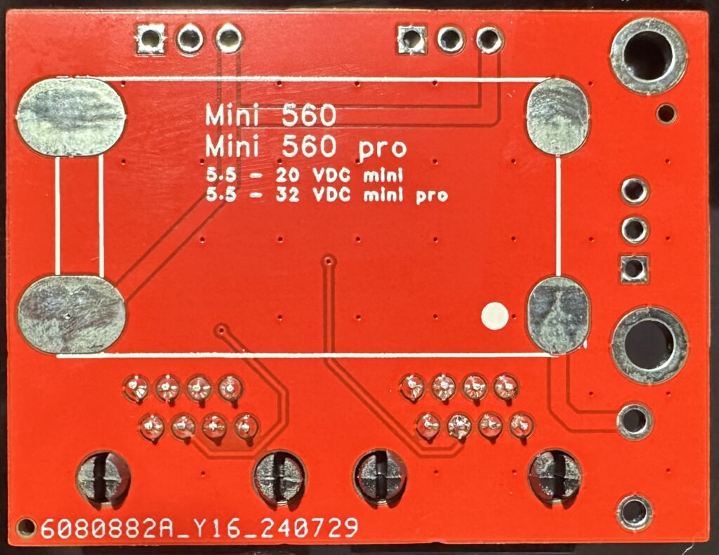
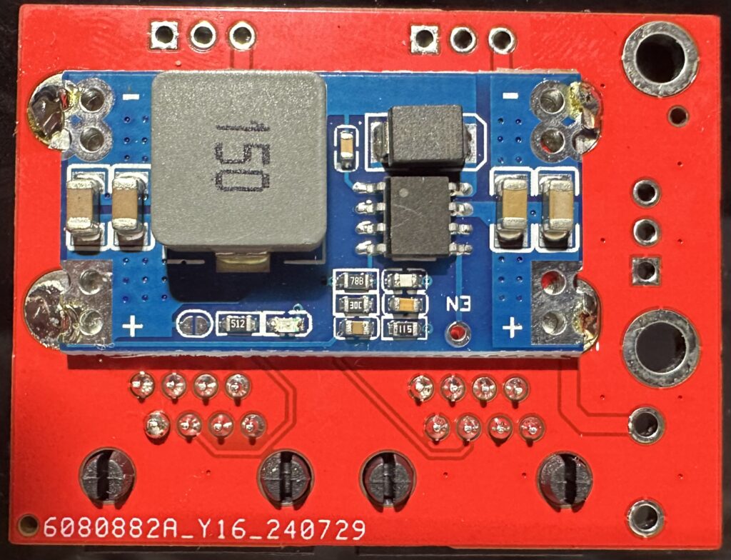
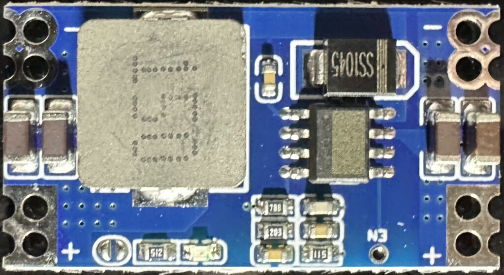
- Modular power supply design using 560-mini or 560-mini-pro components
Setting Up Pixel Link 4.1
Components Needed:
- Pixel Link 4.1 board
- 560-mini or 560-mini-pro power supply module
- WS2812B LED strip or compatible LEDs
- Ethernet cables
- Power supply (voltage range dependent on power module specifications)
- Soldering iron and flux
Basic Setup:
- Solder the 560-mini or 560-mini-pro module to the Pixel Link 4.1 board. Use a good hot soldering iron and apply a little flux to the oval pads for best results.
- Connect your LED strip to the designated connectors on the Pixel Link board.
- Use the RJ45 connectors to daisy-chain multiple Pixel Link boards if needed.
- Connect the power supply to the designated holes on the first board.
Note: All connections need soldering except the RJ-45.
Note: The 560-mini and 560-mini-pro can be found for the best price on AliExpress. The 506-mini is also available on Amazon, though at a higher cost.
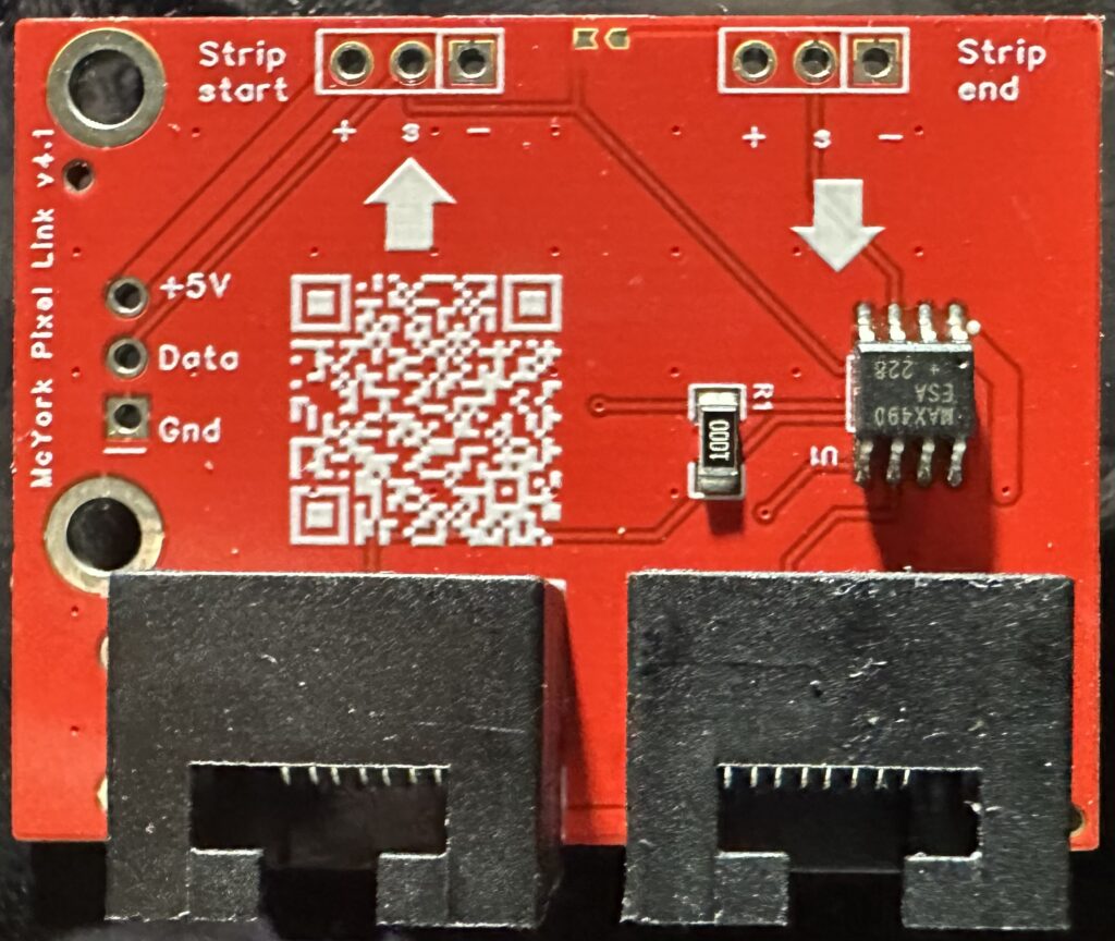
Wiring Configuration
There are obvious arrows on the board that help indicate the inputs and outputs. For example, there is the left-hand RJ-45 and above that an arrow pointing up to the top of the board where the strip start connections are. Then on the right side where the strip end connections are, below that is a downward pointing arrow toward the outbound RJ-45. Just follow the arrows to get your connections correct.
- Power Connection:
- Attach the power supply to the two holes marked + and – to the left of the two RJ-45 jacks when viewed from the top (where most of the writing and the QR code are).
- First Board in the Chain:
- This is typically where you provide power and signal input.
- On the middle left edge, there are three holes labeled +5, Data, and Gnd. Use these to connect your microcontroller:
- +5: 5V power for the microcontroller
- Data: Signal input
- Gnd: Ground connection
- Data Bypass Option:
- There are two tiny pads at the top middle of the board between the strip start and strip end jumper holes.
- If you solder bridge these two pads together, the data will bypass the strip connectors and directly exit the outbound RJ-45 jack.
- This is useful when you want the signal converted to RS-485 but have the first segment of lights some distance away from the microcontroller.
- Subsequent Boards:
- Connect using ethernet cables to the RJ-45 jacks.
Power Considerations
- The first board in the chain is where it’s common to provide power.
- Other boards will receive power over the ethernet cable until either power or voltage limits are reached.
- When limits are hit, you’ll need to inject power again using the same + and – holes as on the first board.
- The distance between power injections is determined by trial and error, or mostly by the number of LEDs per board (or total) and the length of the ethernet cable segments.
Using Multiple Boards
Pixel Link 4.1 supports daisy-chaining multiple boards for extended installations. Remember these key points:
- Use standard ethernet cables to connect boards.
- Monitor power requirements and inject power as needed along the chain.
- The first board setup differs slightly from subsequent boards, particularly in terms of power and signal input.
Compatibility and Safety
- Pixel Link 4.1 is designed for use with WS2812B LEDs and compatible protocols.
- The boards are not compatible with standard ethernet equipment. Connecting them to routers, computers, or network gear could result in damage.
- Always ensure proper power connections and avoid reverse polarity.
Project Journey and Future Developments
Pixel Link 4.1 seems to have solved the original goals of the project envisioned as far back as 2014. Now, a decade later in 2024, it’s gratifying to see how persistence has paid off. This journey demonstrates that with dedication and continuous improvement, even complex technical challenges can be overcome.
As I continue to refine and expand the capabilities of Pixel Link, I’m excited to see how users will push the boundaries of what’s possible, creating even more immersive and expansive lighting installations. The project remains open to feedback and suggestions from the community, as there’s always room for innovation and improvement in the world of long-distance LED control technology.